|
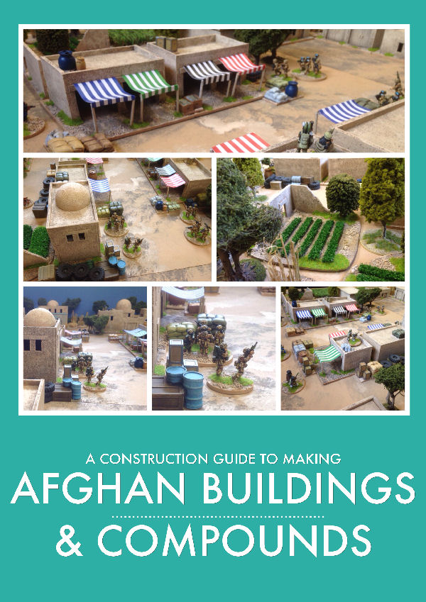
Generic, All-Purpose, Incredibly Useful, Modern Wargames Buildings
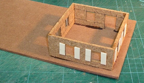
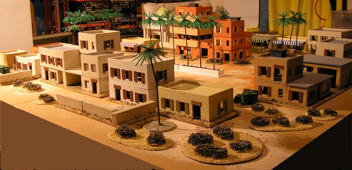
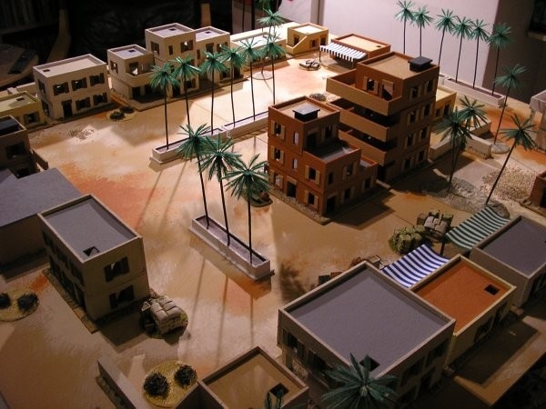
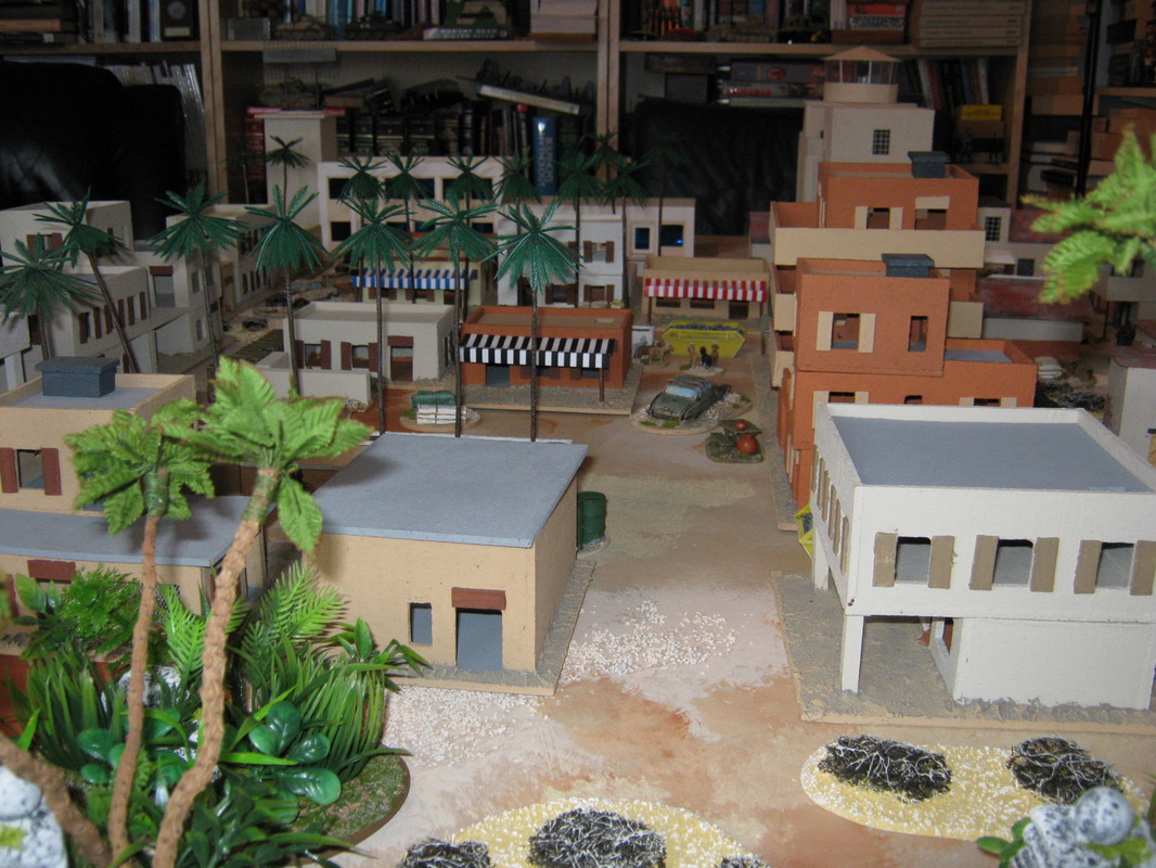
I’ve wanted to make this kind of building for a long time but, until recently, there was always something more urgent to get on with. However, a combination of not being able to paint for a while and the arrival of a set of inspiring modern rules meant that I finally had the time and enthusiasm to embark on this long-anticipated project. The basic idea is to build a set of generic modern buildings that can be used for any number of conflicts in those parts of the globe that used to be referred to as Third World but are now called Less Economically Developed Countries (LEDCs). I plan to use the finished layout to represent places as diverse an Iraq, Afghanistan, Mogadishu, Several nameless African towns and Saigon. They may even see service in the near future as a colony settlement for a Cyberpunk game. Wherever humans have thrown up cheap, blocky, concrete buildings (London?) and then decided to fight each other these models will let me recreate the setting in miniature. The set will be composed of two types of buildings. The first group are flat roofed, Middle Eastern styled buildings; essentially concrete versions of adobe structures that have existed in that part of the world for centuries. There will be the occasional dome or striped awning to add variety. The second group are similar but have corrugated iron, gabled roofs; a type of building more common in Africa. Both types look fine side-by-side and will hopefully evoke the right atmosphere regardless of the actual game setting. I’m not going to explain the basic construction, these buildings are just boxes, and I’ve given detailed explanations of working with cork in numerous other articles. I have added some plans that can be downloaded and followed. Those of you who are particularly sharp will see that I’ve departed from my drawings on several occasions and there’s no reason why you shouldn’t do the same once you’re comfortable with the basic procedures. I will explain some design choices I made this time around. These are minor changes to my technique based upon experience gained from gaming with my model buildings. Some of these were implemented in the building of my Baltimore Projects buildings which I’m still working on. 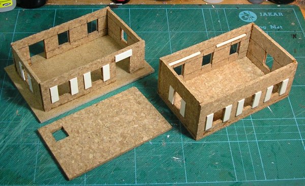
Firstly, drop-in floors, like those in the city tenements, prove awkward during play and I try to avoid them now. With this build I don’t expect anything to be taller than two floors so I am making each level separate and self-contained. Upper stories will be attached to their floors which will lift off with them. This makes placing figures inside buildings a simple, one-handed affair. Conversely, flat roofs are better as drop-ins rather than lifting off with their parapet attached. Making them this way allows the building to be much stronger. They do need some way to facilitate lifting them out however. For this selection of buildings I have cut access holes that do the job; for the Baltimore buildings I added attached chimneys that acted as handles.
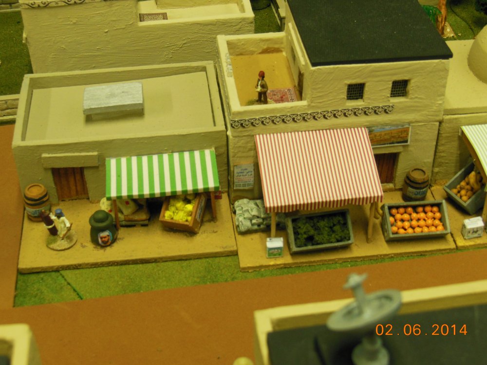
Secondly, I no longer add locating lugs to the underside of detachable floors. These also proved difficult during play; requiring two hands and some degree of dexterity and care to re-seat them properly. Several of my buildings were damaged as a result. They are not needed anyway; players do not tend to dislodge building parts during play. I still use them for overhanging flat roofs where the positioning is important for aesthetic reasons. About the only things that are new in this build are the shop awnings. The awnings were made from a basic pattern printed out on 70gsm copier paper and cut to size. Although the patterns are easy to make I’ve included the ones I’ve done in case you want to use them. I cut the awnings so that they were 120mm wide and 70mm deep. This allowed for a 50mm awning depth with 10mm at the front for an overhang and 10mm at the rear to attach them to the building with. I originally tried to cut the front of the awnings with crimping shears to give a wavy edge to them. Unfortunately my crimping shears were cheap plastic ones I’d bought years ago to make knights’ pennants with and weren’t up to the job. If you have a decent pair of your own shears you may want to give this a go as I think it will look effective. The awnings are fixed to the buildings with wood glue. I cut a strip of card 120mm x 10mm for each awning and painted it brown to resemble wood. This was glued underneath the awning, (on the unprinted side) along the back edge. When the glue was fully dry I folded the paper 90° along the long edge of the card strip and attached it to the building, sandwiching the paper between the card and the wall. You can see the finished awning in this photo: 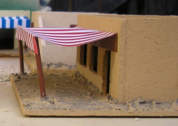
The supports for the front of the awnings were made from some Plastruct square rod with a hole running through it that I had lying around.
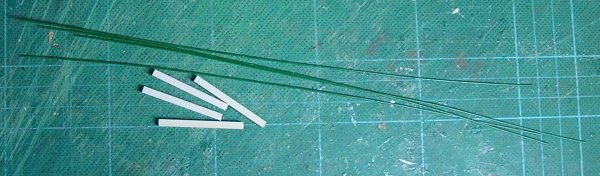
The rod was cut into 40mm lengths and a bent piece of florists’ wire was fitted into both uprights before being secured with super glue.
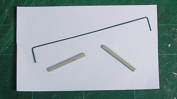
I realise that most people won’t have bits of Plastruct lying around and, indeed, I only had enough for two awnings so I made some more uprights from bamboo skewers. The skewers were very easy to drill by hand with a pin vice.
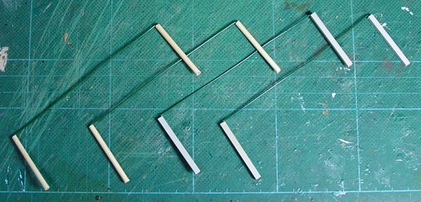
Once everything was set the front supports were painted and glued to the awning and building base.
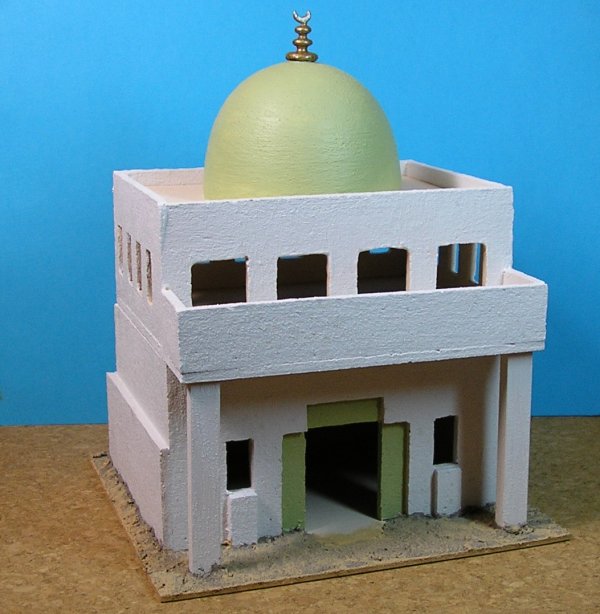
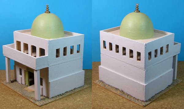
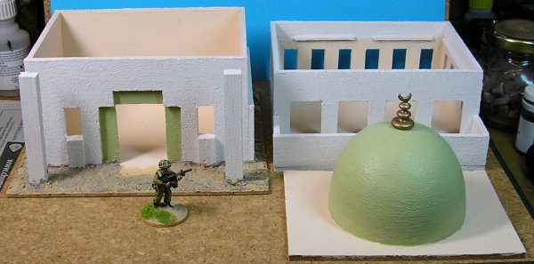
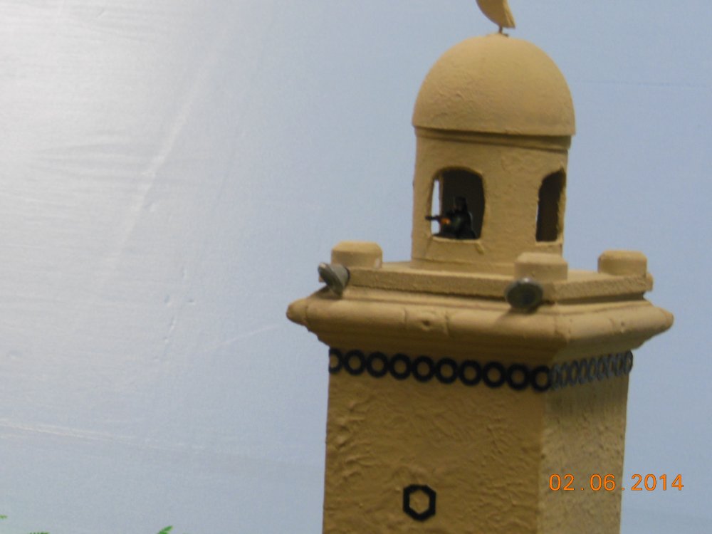
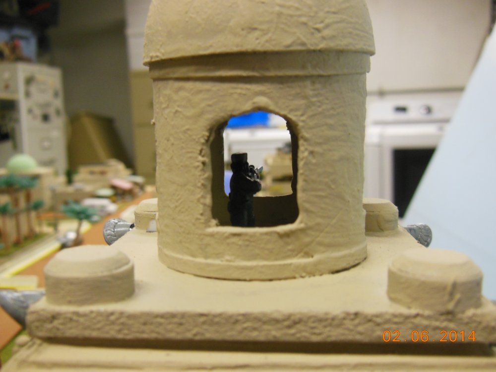
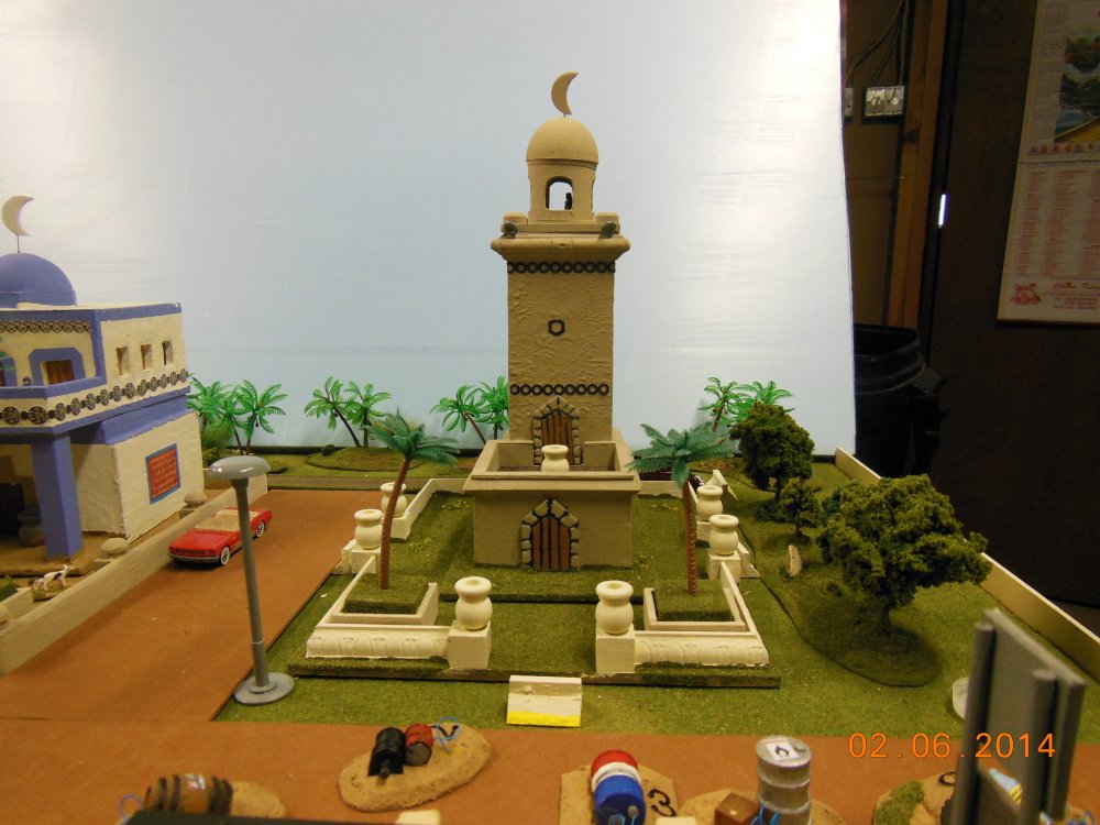
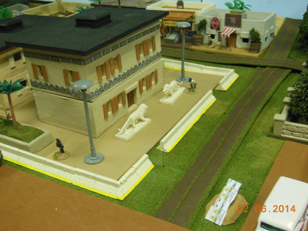
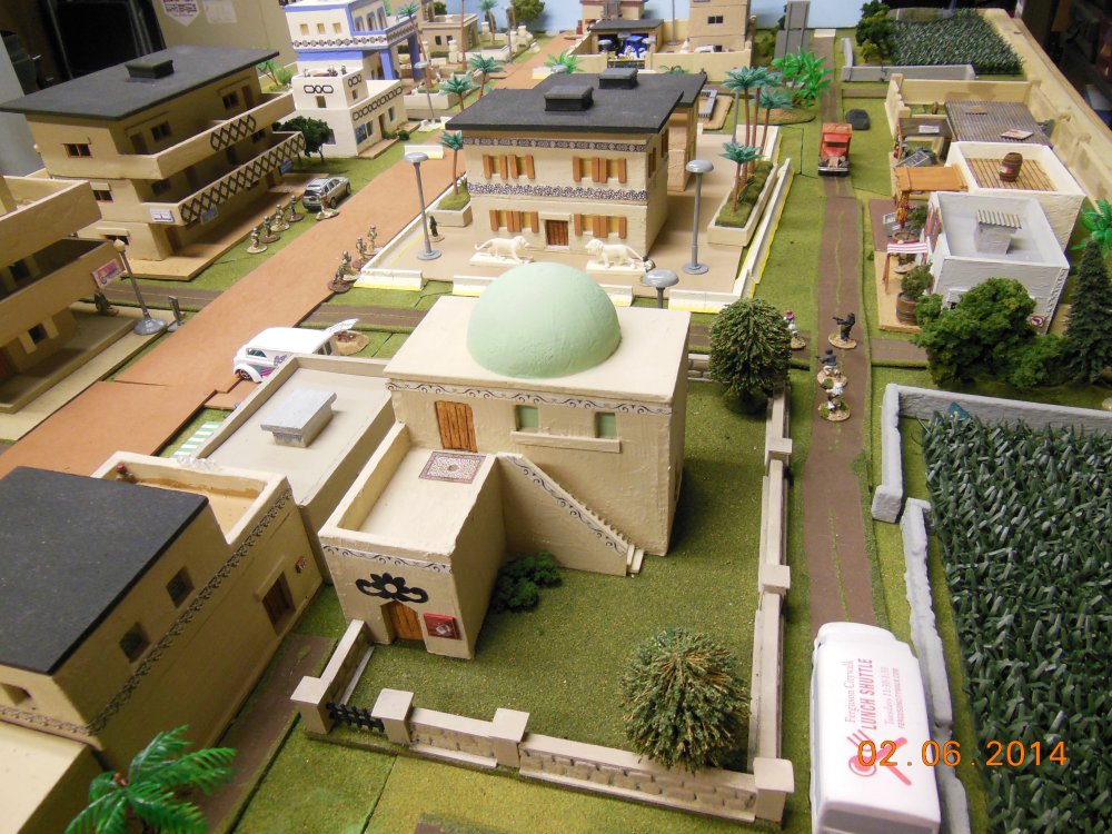
Mosque
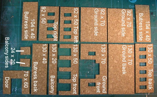
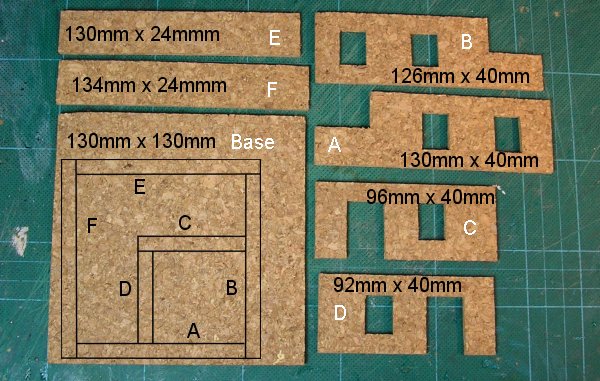
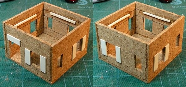
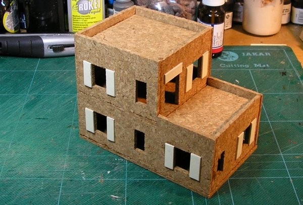
Here's the simple cutting plan for the Mosque. It doesn't show the 130mm x 130mm floor for the top section or the drop in roof which needs to be measured after construction. The 'buttress' sections are designed to go on the outside of the ground floor walls once they've been assembled. The 'door' is an insert that is glued behind the bigger doorway. I've added two small window off-cuts below the front ground windows to give more texture to the front of the building. The small windows are 20mm high and 10mm wide. They are evenly spaced at 10mm intervals. Doors are 30mm x 20mm as normal. The front door is 50mm high at the tallest point and 50mm wide at the base. The insert cut out is 30mm x 40mm. As always the top floor isn't glued to the ground floor so it can be easily removed during play. The inset roof is supported by matchsticks glued inside the upper walls as with most of my buildings. The dome is a resin one made by Ian Weekley and available from several retailers. There are various plastic, polystyrene or wooden alternatives in many craft shops. It is glued to the drop in roof with super glue and acts as a handle to remove the roof with when needed. The wooden posts are 70mm tall and glued to the base. They are not glued to the top floor so that it can be removed. 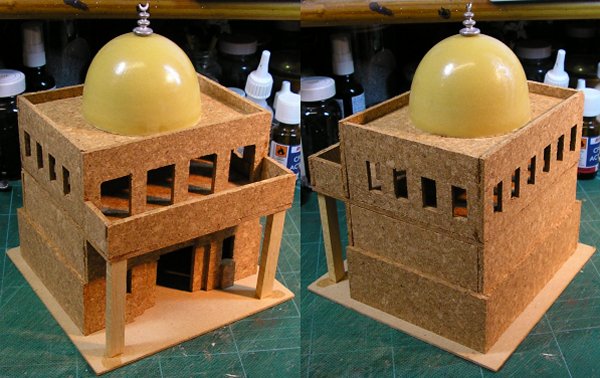
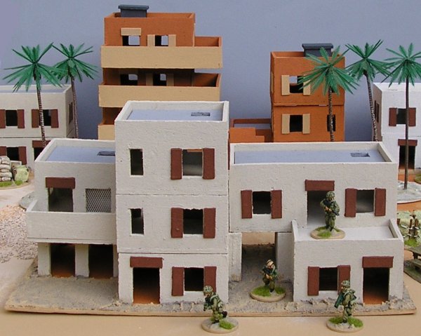
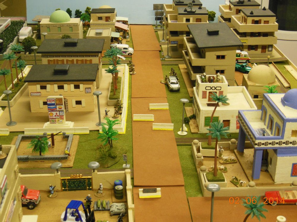
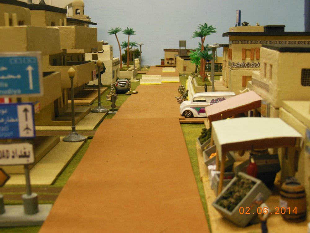
Modern Buildings – Streets
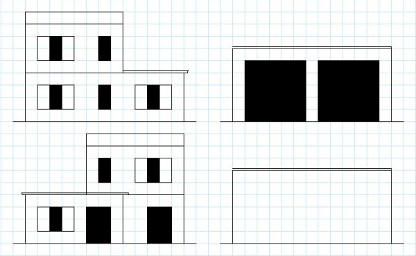
The single buildings are very simple structures to make. To off-set these I want to try something a little more complicated that will still compliment the originals and be just as versatile. I’ve decided to make some ‘street sections’. These will be multiple buildings on a single larger base designed to replicate a much more densely built up area. They will still need a small footprint on the table and they will need to incorporate the original buildings’ style elements in order to blend in. The challenge will be to make an interesting terrain piece that offers several height options whilst still being sectional for figure placement yet sturdy enough to game with. I need to have four of these in the ‘desert’ style, enough to delineate a sizable area on the games table. Each one will be different, hopefully with a ‘theme’ to it. The first street section. I’ve settled on a base size of 300mm x 150mm for each section. This is the same as two large standard bases but I’m hoping to get three to four buildings on each section. I took a while designing the street on paper, here’s my original drawing. 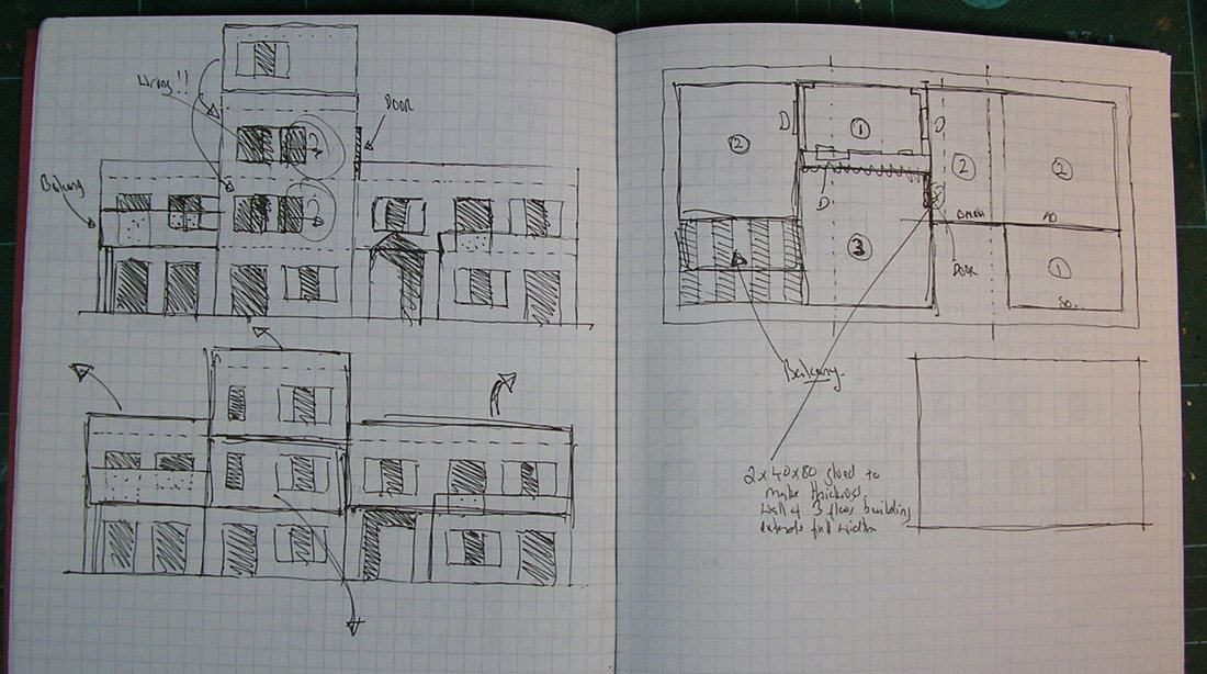
Here’s the original transferred to cad drawings. Each square on the grid represents 10mm. The windows are not drawn accurately, they are actually 15mm wide and 20mm tall, however with their shutters they take up a 30mm width so it’s easier and quicker to draw them the way I’ve done them on the plans
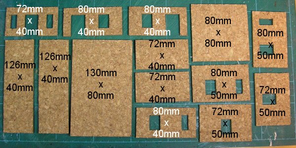
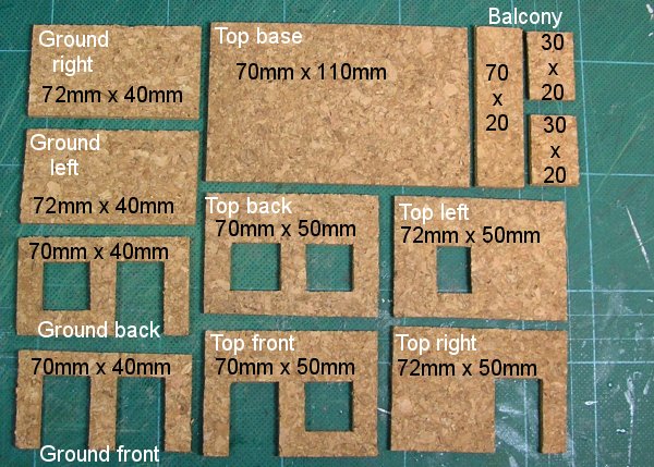
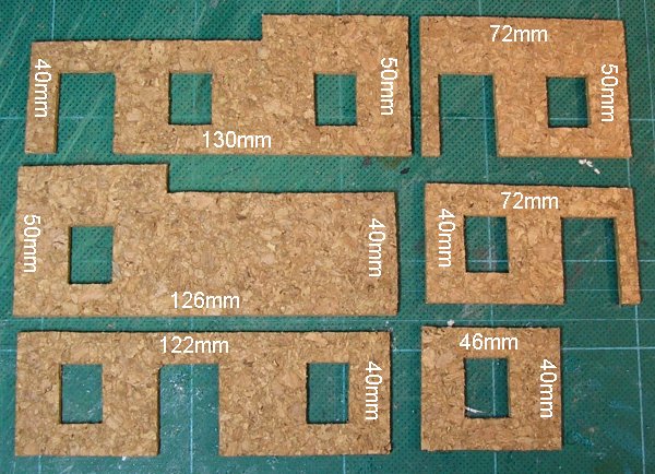
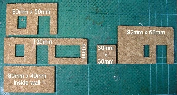
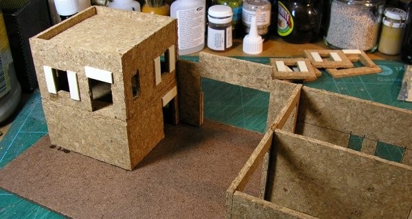
I’ve decided to start with the section on the right of the street, here’s the first cutting plan.
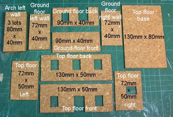
The parts shown above make the two-floor section and the archway. Adding the parts below completes the section with the low front building. The left wall of the archway is made by gluing the three pieces of cork together so that you get a 12mm thick component.
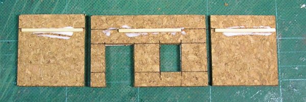
The front wall is 80mm x 50mm and the sides are each 46mm x 50mm.
Everything is glued as normal using super glue for the cork and wood glue for the card shutters and matchstick roof supports.
The top part is not glued in position so that it can be removed during play allowing access to the ground floor.
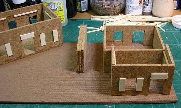
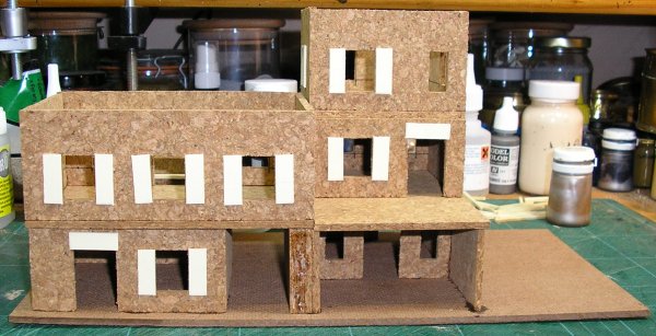
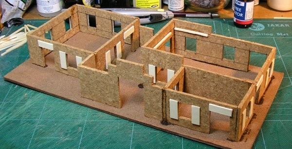
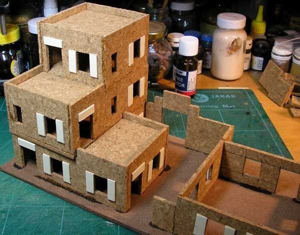
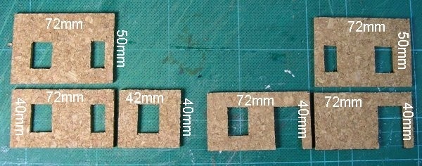
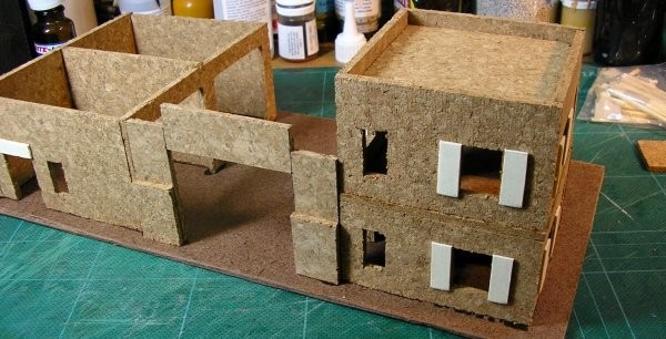
Next comes the tall, three story building in the centre. The photo above shows the measurements for all three floors whilst the photo below shows where each piece goes. The 'Middle front' wall is actually upside down in the picture, the shuttered window will end up on the right side of the wall, not the left.
Since the existing part of the structure is going to dictate the position of the next it's necessary to use it as a guide. I attached the right wall to the left wall of the archway and built the rest of the ground floor off from it. The other floors are then assembled and stacked on top.
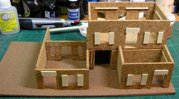
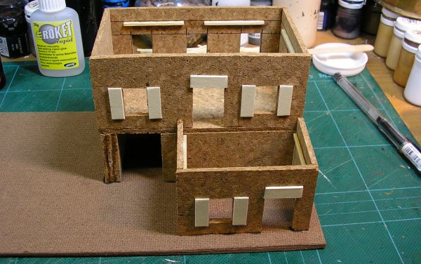
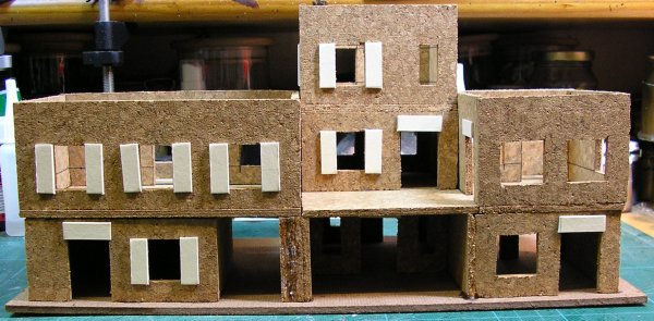
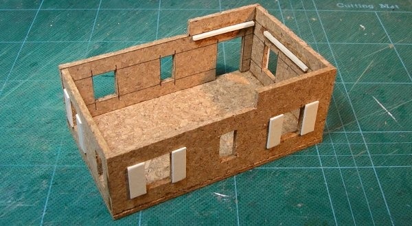
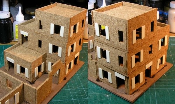
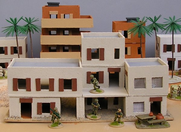
Here's the completed front.
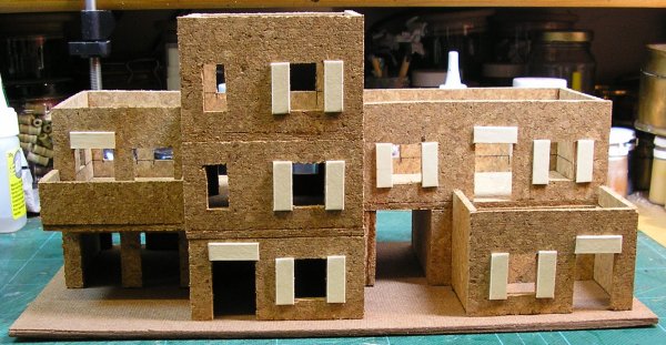
And the completed rear view.
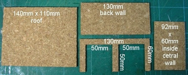
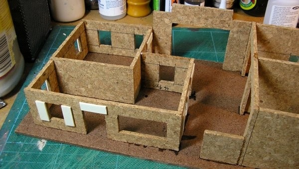
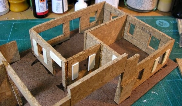
This is the cutting plan for the last part. Once again the ground floor is built first taking its positioning from the existing building.
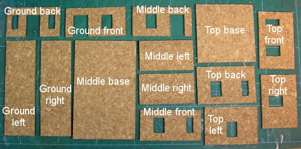
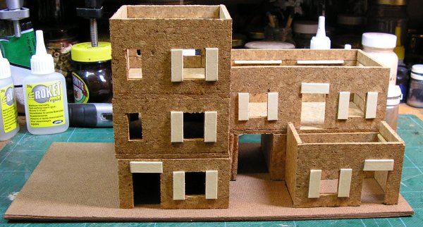
Here's the finished street apart from the drop in roofs. Front view...
And rear view. The roofs need to be cut to the size the apertures ought to be and then trimmed to fit. There will always be some degree of error in the sizing to begin with.
I painted the walls of the building with Dulux Weathershield which is a textured paint and once everything was dry I glued some aluminium car body filler mesh inside the 20mm square windows to act as grills. Apartment Complex
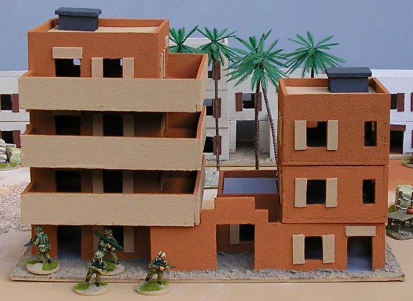
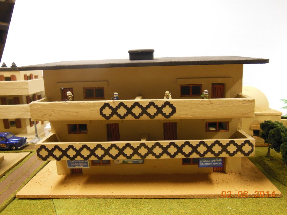
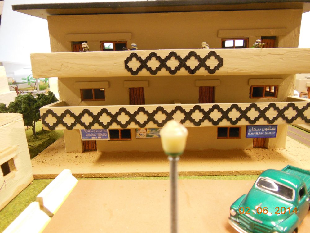
My second 'Street section' is an apartment complex comprising a balconied apartment building and another, simpler building on a base with a small open area between them. 
Here is a plan of the front of the apartment complex; each square is 10mm. The shaded area is a wall and gateway that runs along part of the front, joining the two buildings. I've put it in as transparent so the building behind isn't obscured too much.
Here is the plan of the back; again, each square is 10mm.
Here are the pieces needed to make an apartment block level. You will need to make a set of these for each level you want your block to have except for the ground floor which is different because there's no balcony and the top floor where the walls must be 50mm high, not 40mm, to allow for the drop in roof.
The insert diagram shows how the walls are placed and in which order they should be glues (A-F). The balcony walls are glues outside the base, not on top of it. 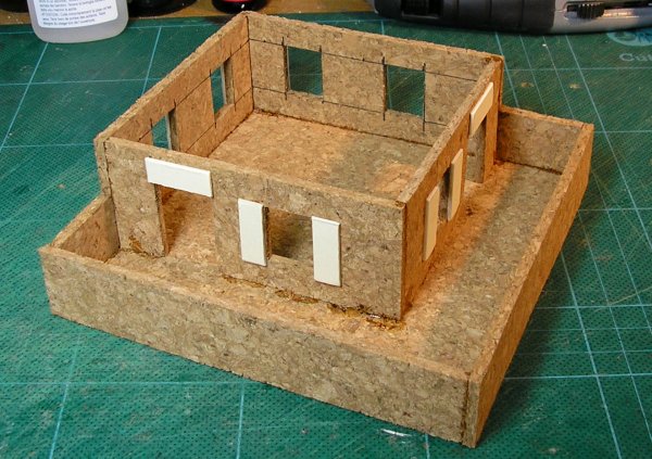
Here's what a completed level looks like.
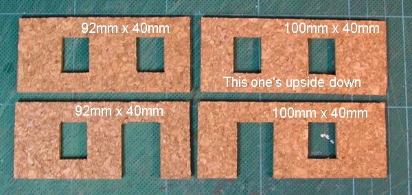
These are the pieces for the ground floor. The 100mm lengths go outside the 92mm ones with the doors directly underneath the doors on the balcony levels.
The ground floor should be placed 10mm in from the corner opposite where the balconies will be. I've chosen to have one of my balconies over hang where the central open space will be to help unify the terrain piece and to avoid having an unused 40mm border along two sides of the base which would be a waste of space. If you have your apartment block on it's own base you will have to live with this or make the base smaller so the balconies overhang it.
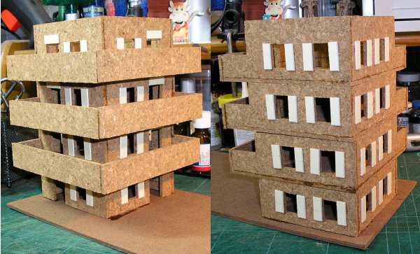
I planned three balconies for my apartment block. Here it is assembled, the floors are separate of course so figures can be easily placed on each floor.
Now onto the rest of the base. 
Here are the elevations of the second building. This is an 'L' shaped structure that rises in tiers like a spiral stair. Each square is 10mm.
This is the cutting list for the ground floor.
Here's the new ground floor assembled and the walls put in place to tie the two buildings into a cohesive whole. Without the walls the buildings may as well be on separate bases which would mean they'd lose the dynamic of the space between them. The open spaces on a terrain piece are as important as the built up areas.
Assembling the ground floor wasn't as easy as I'd hoped. If I do this design of building again I will make the other part of the 'L' the initial box and have the 50mm tall section as an add-on. As it is the building is crooked which will have ramifications for the upper floors. Oh well, live and learn. 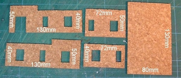
This is the cutting list for the middle floor.
This bit's easy.
The top floor is just a regular box 80mm square and 50mm tall. The short walls need to be 72mm wide.
Both upper floors stack together neatly. They're not glued so they can come apart and allow figures to be placed inside them. The drop-in roofs are also unglued.
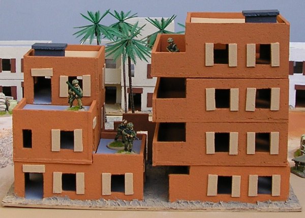
Once everything is stacked up in place it looks suitably impressive. Unfortunately the crooked ground floor means the middle floor overhangs it a bit. I had to choose between making the upper floors crooked too so all the walls matched or just living with the overhang. I chose to live with it because these buildings are wargames scenery, not scale models and strength gained from having regular top floors, is more important to me than a slight imperfection.
From this shot of the other angles you can see that the overhang is worse at the front; even so I doubt it will be noticed during play.
Here's everything finished apart from some air conditioning units which I want to put on the roofs to act as handles so they can be easily lifted off during a game.
The back view.
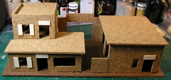
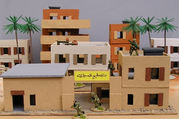
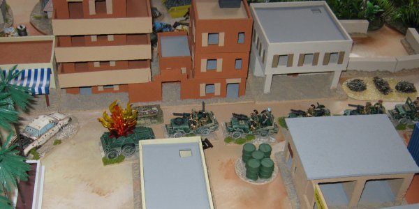
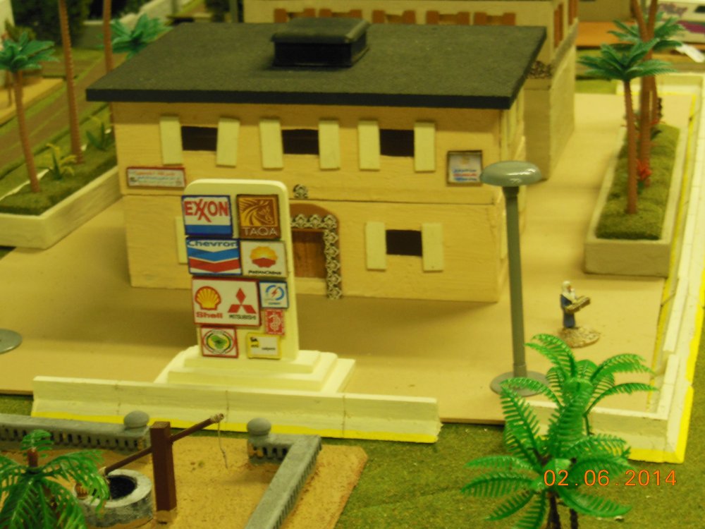
Taslih Alsayarat
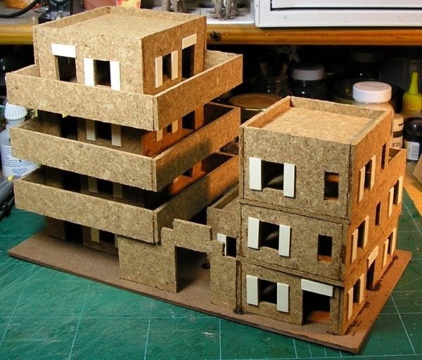
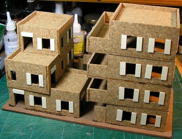
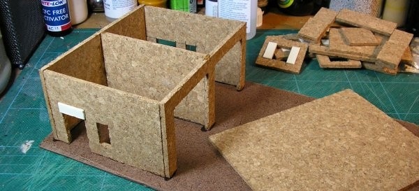
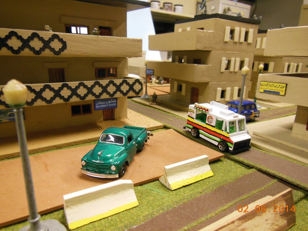
This is the third of my four 'street sections' and is meant to be a car repair shop (Taslih Alsayarat in Arabic). It consists of a set of garages/workshops at one end and a parts shop with offices or living quarters at the other end both separated by a courtyard. 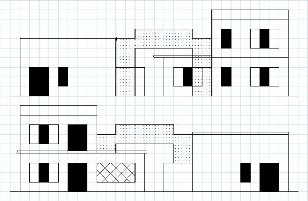
There is a wall with an archway joining the two sections on one side which I've indicated with a half tone fill above so it doesn't obscure the details of the building behind it. The other side has the buildings separate with just a 30mm x 30mm wall placed against the garages to make the gap a pedestrian entrance and not a vehicle one. However, since the yard is actually very small I removed my 30 x 30 wall after everything was built to make it look like there was more room for cars. You should probably not fit it to begin with, just ignore all references to it in the photos from now on.
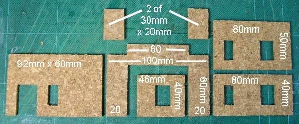
Here is the cutting plan for one side of the complex, the side with the archway shown in the upper elevation above.
This is the cutting plan for the other long side shown on the lower elevation above. Don't do the 30mm x 30mm piece.
These elevations show the views along the short axis. The top one is the view if you look from the shop end towards the garages and the lower one is from the opposite direction. Obviously, in reality the buildings are lined up and would obscure each other so I've split them up.
The rest of the garages block. The inside central wall runs from back to front where the middle pillar is.
The final pieces for the shop/offices block.
I began with the garages as they're the simplest part and the easiest to position correctly on the base. As usual for these pieces, the base is 300mm x 150mm. Everything else will take its positioning from the garage block.
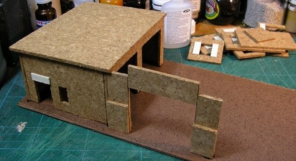
Next I attached the archway. The 30mm x 30mm pieces have been glued onto the lower parts of the uprights to add some texture detail and strength to the wall.
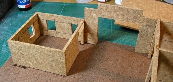
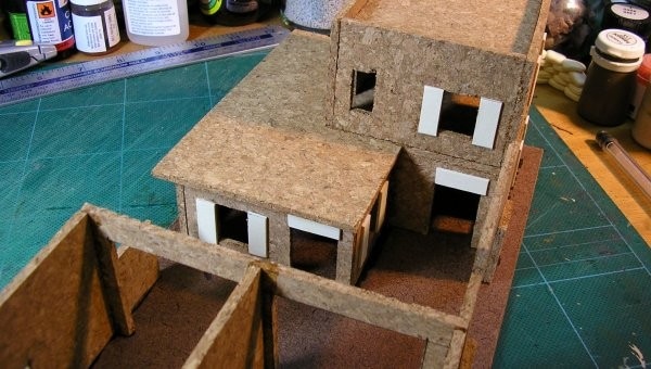
The bottom part of the two story office building was added next. This needs to be a discrete structure from the rest of the offices/shop assembly so that it can support the upper floor and so that the whole thing remains true and square. I found with the apartment building that trying to construct complex shaped buildings as a whole rather than in sections creates many problems and the finished structures suffer as a result.
The short walls align with the short sides of the base board and go inside the longer walls. This is fairly obvious because of the position of the door but if you get it wrong everything else won't fit. 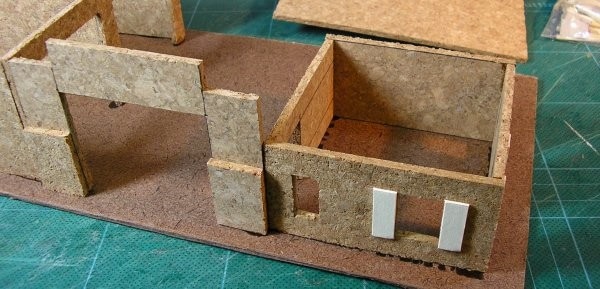
I don't add interior doors (or other detailing) to the buildings as the rules I use don't require them; there is nothing stopping you adding them if you want to however.
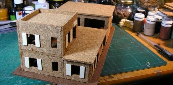
The upper floor was made next. It was glued to an 80mm x 80mm base that isn't shown in the cutting plan and then just sits in place so it can be remove during play to allow access to the room below.
Make sure you assemble it so the windows match up.
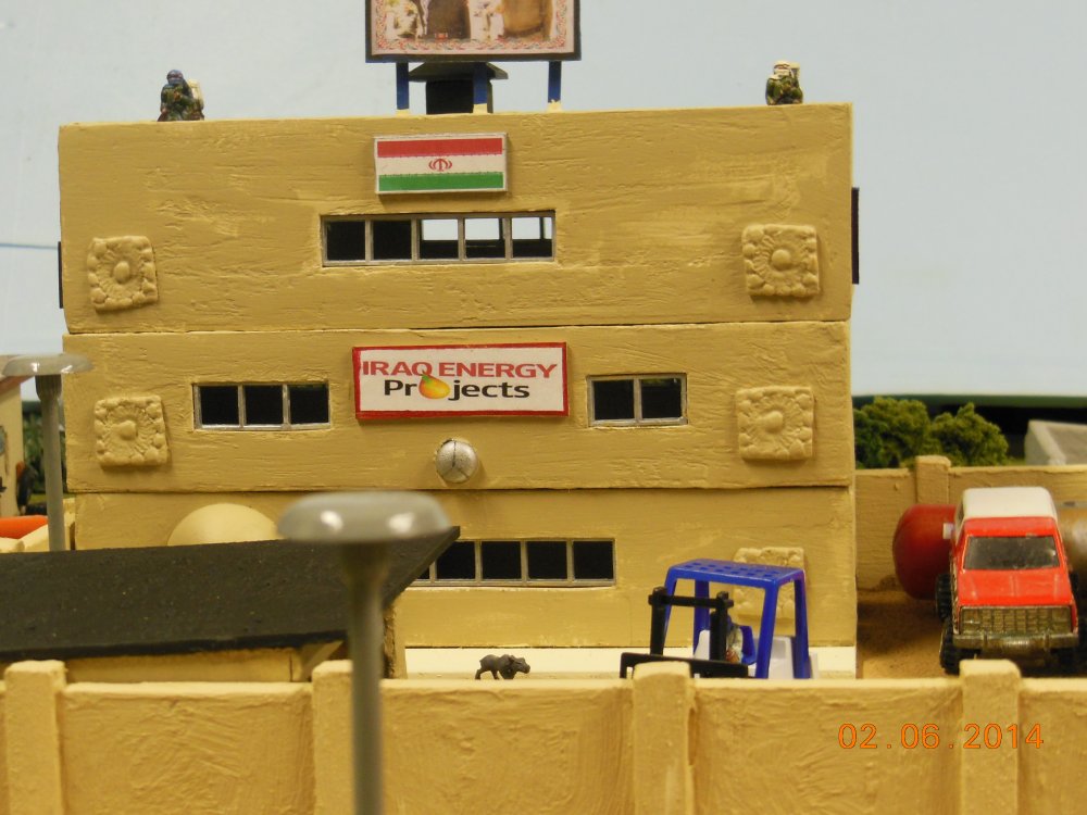
Lastly I added the shop (and the accursed 30mm square wall). Because the bottom part of the offices was already in place and secure it was an easy job to get the shop to line up properly.
All done.
The roofs need to be cut to fit. The garage roof overhangs all the way around so it was cut out at the beginning and is included in the cutting plan. The inset roof for the offices ought to be 72mm square but may need some trimming down (for the first time ever mine didn't!). The 'L' shaped roof for the shop will need to be measured. I gave mine a 5mm overhang all round and it ended up as 140mm x 83mm on the two longest sides with the cut out section measuring 85mm x 30mm. The edge facing the arch was 55mm and the short edge on the left in the picture was 53mm.
None of the roofs are glued down and you will need to cut a hole in the inset roof or add an air conditioning box to allow it to be removed easily. I haven't decided which I'm going to do yet. 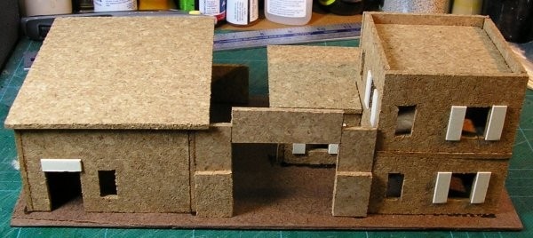
Once the paint was dry I added a screen to the parts shop window with some aluminium car body repair mesh.
|
Awning artwork:


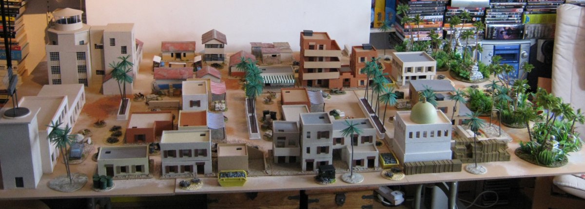
Other People's Buildings
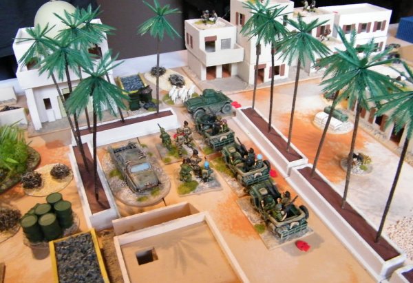
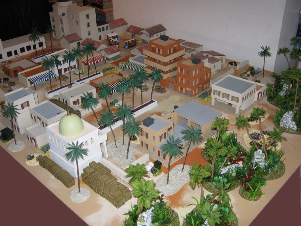
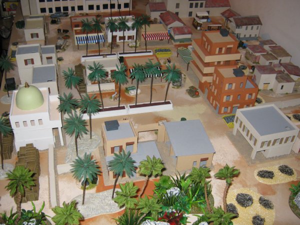
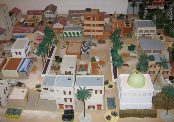
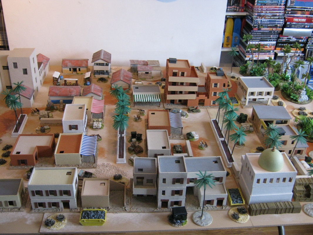
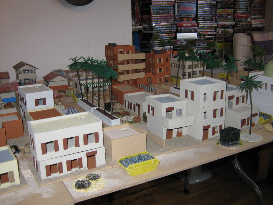
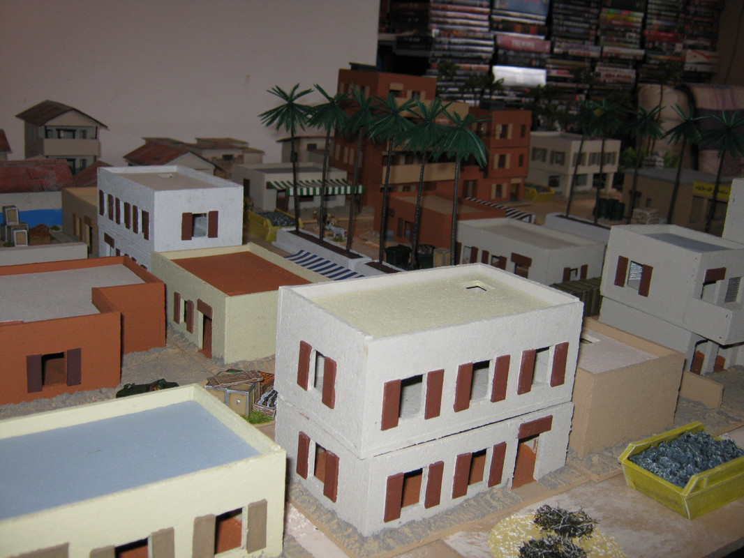
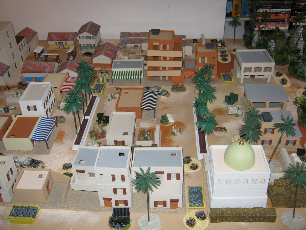
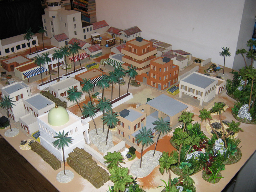
Once again Robert Provan (Toaster) has shown that he's more than capable of following my plans. Here are some photos of his versions of the street section, apartment complex and car repair shop added to his existing buildings. 
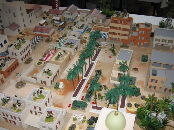
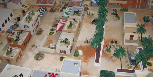
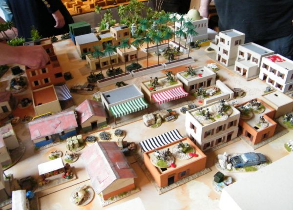
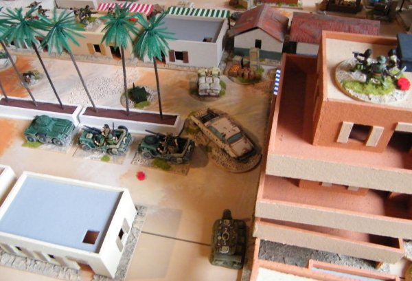
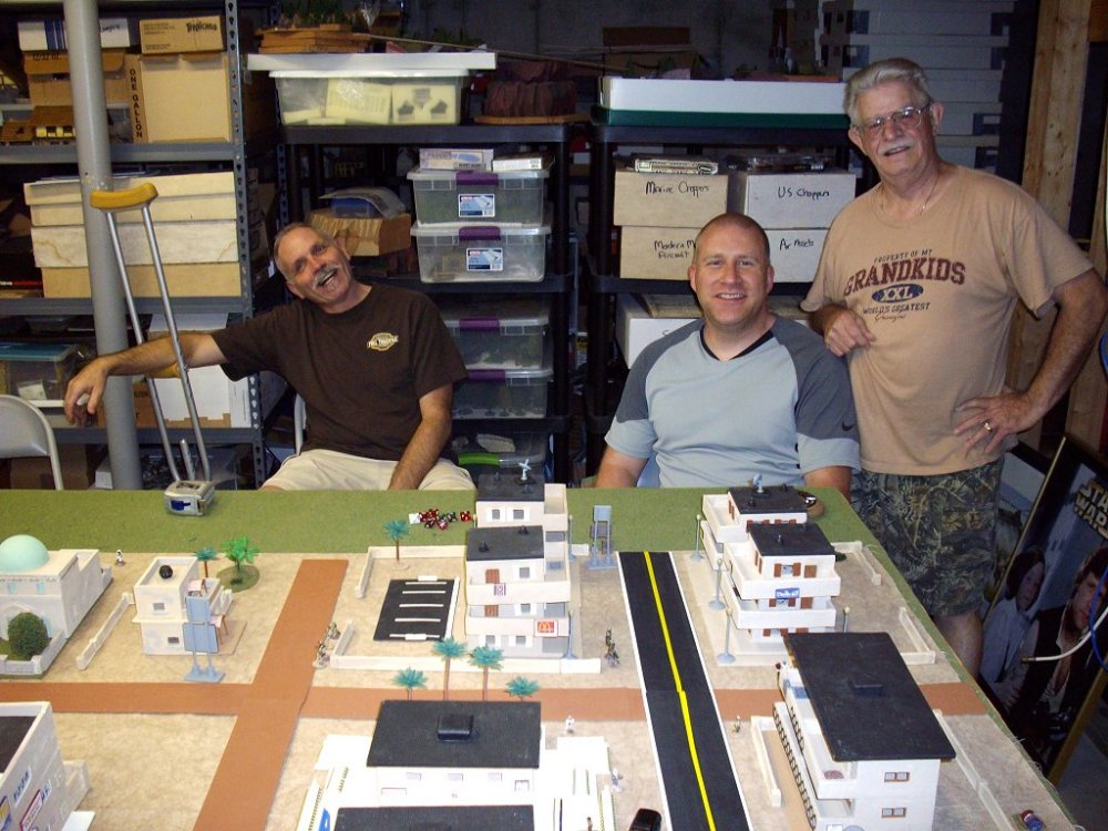
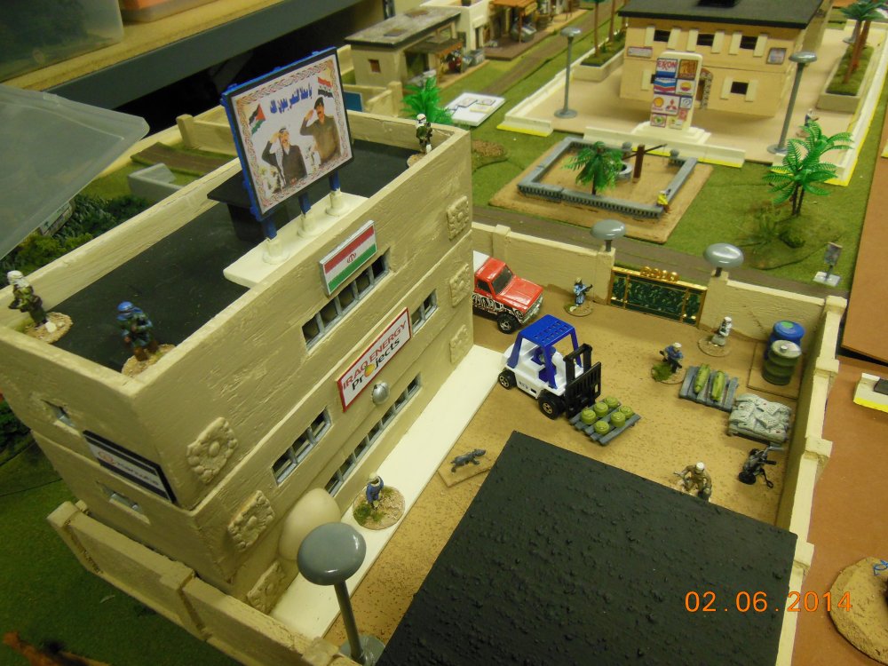
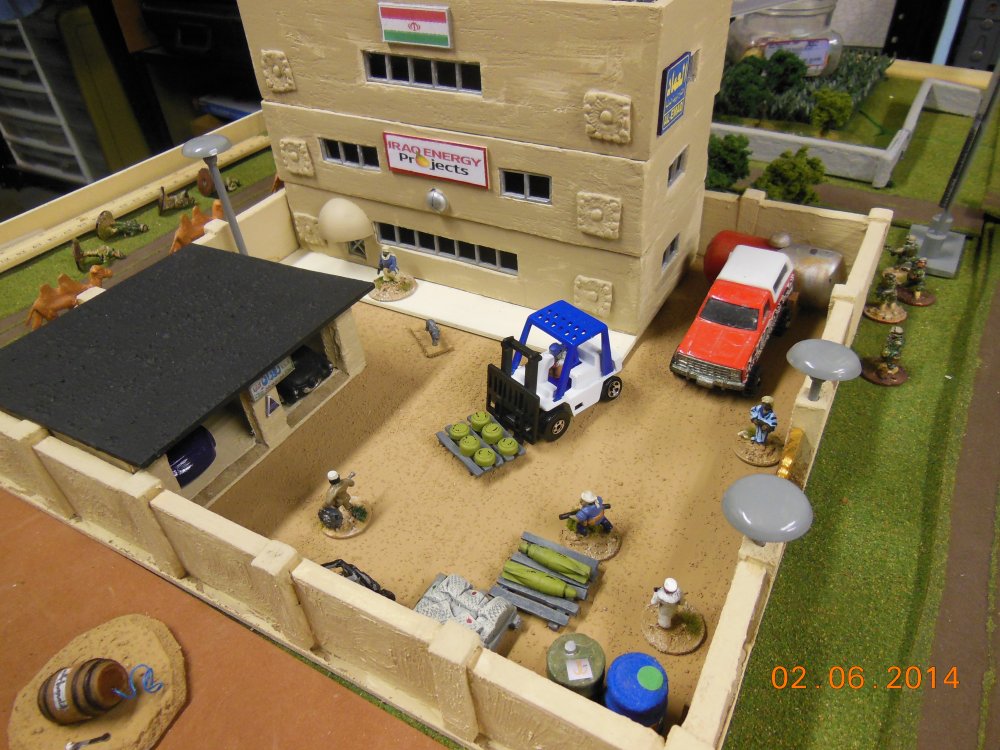
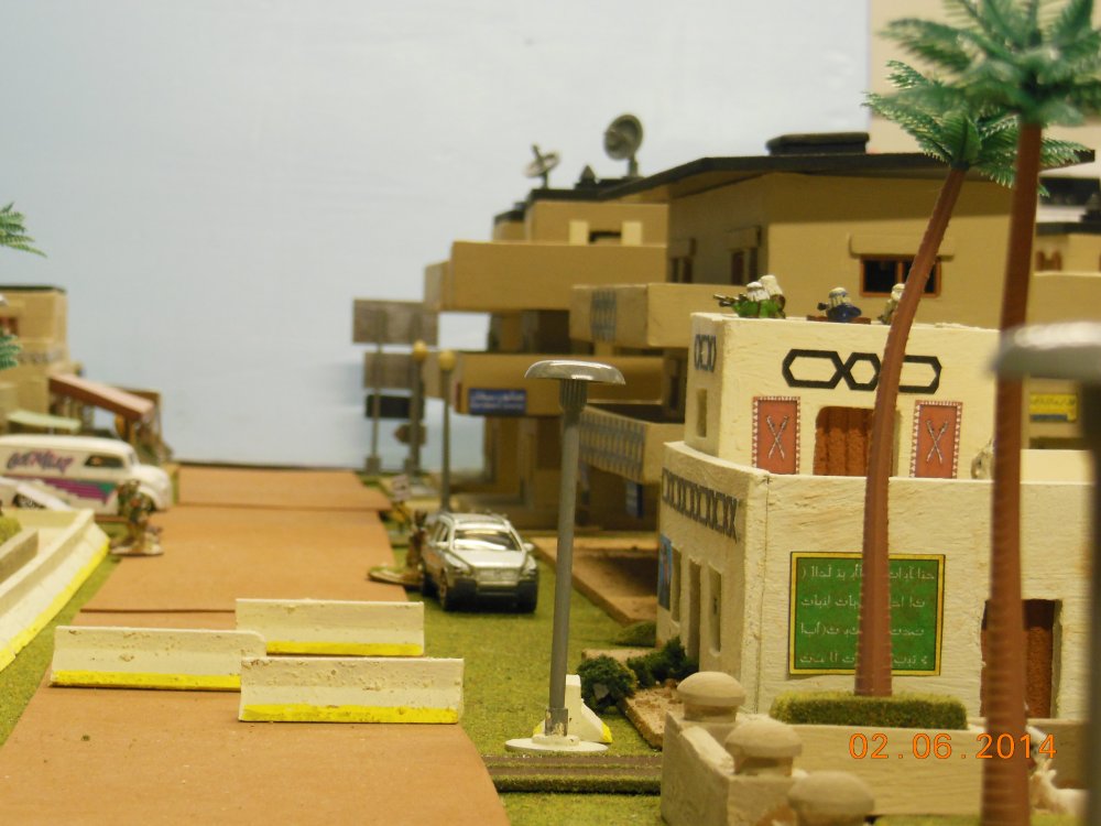
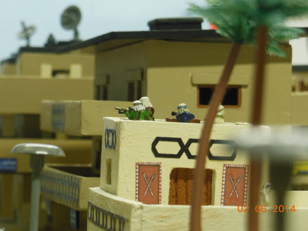
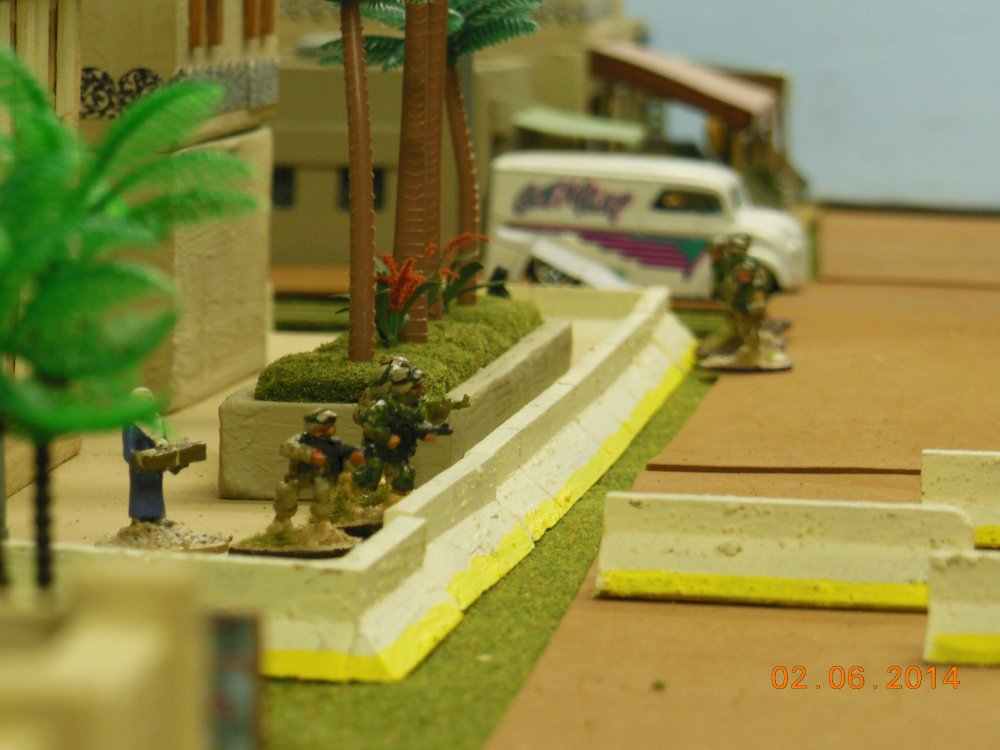
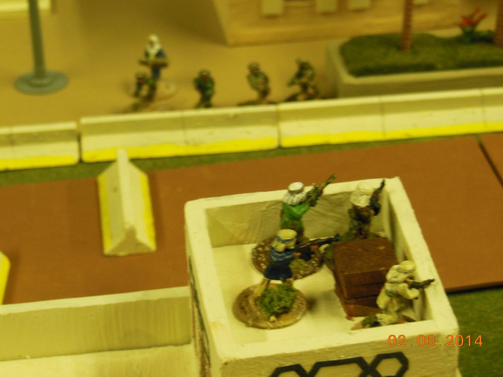
Bill Gaynor and his friends in St. Louis Missouri staged a Force on Force game using buildings based on my plans. Their improvements to my basic boxes really make their buildings shine in my opinion.


|